Multi Battery Isolator Wiring Diagram
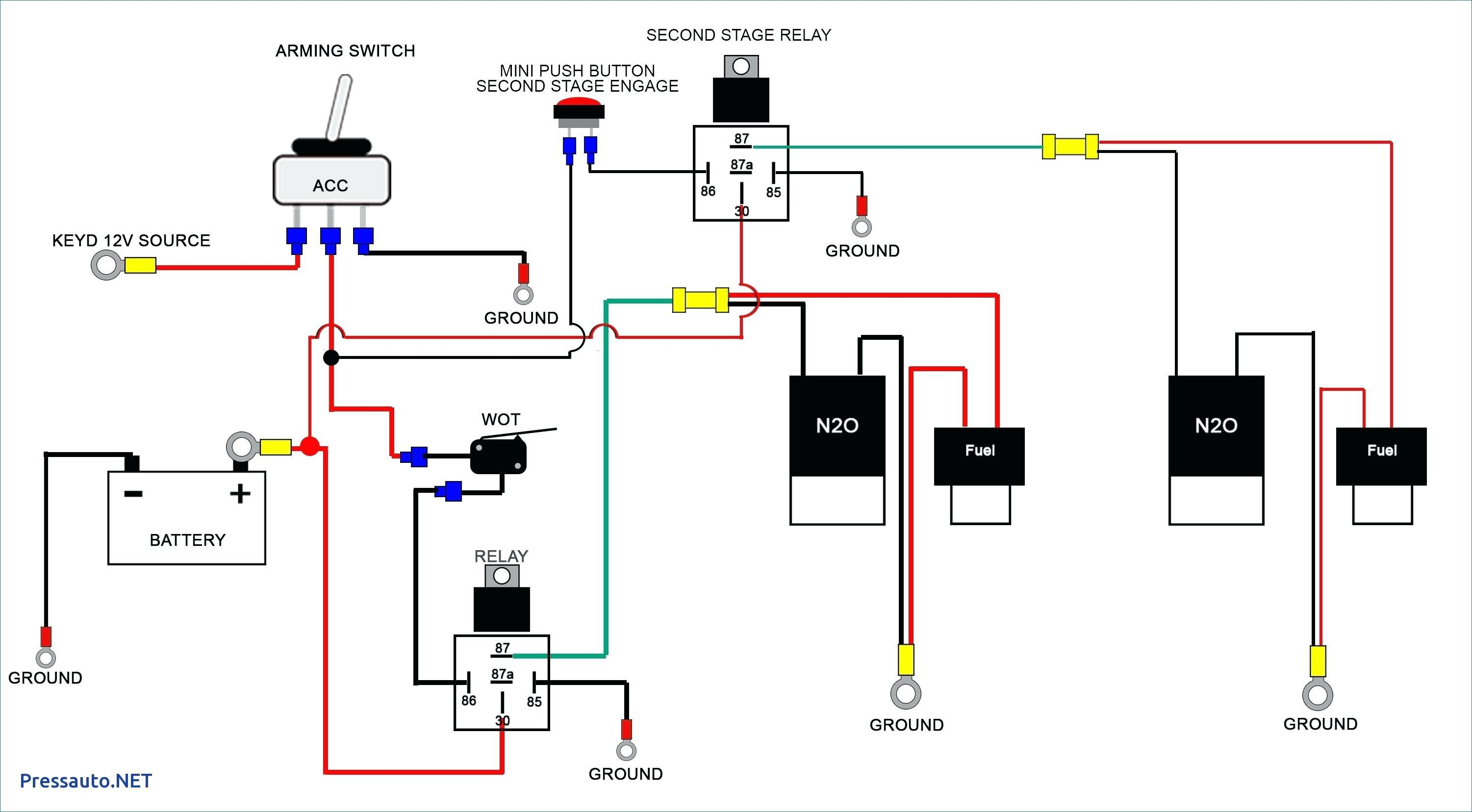
Quickcable offers an installation wiring The first component is symbol that indicate electrical element from the circuit.
Multi Battery Isolator Wiring Diagram
In diagram, being careful not to over torque the.

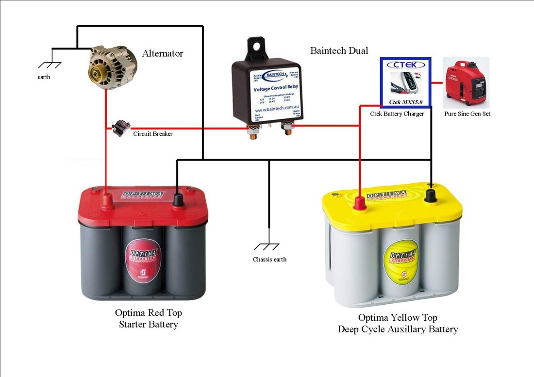
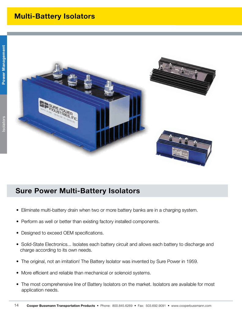
Multi battery isolator wiring diagram. How to correctly wire multiple 12 volt batteries to an rv. Dual battery isolator wiring diagram dual battery isolator circuit diagram dual battery isolator switch wiring diagram dual battery isolator wiring diagram every electric structure is made up of various unique pieces. Isolators actually enhance battery switch applications because each battery can still be charged independently when the switch is connecting either battery.
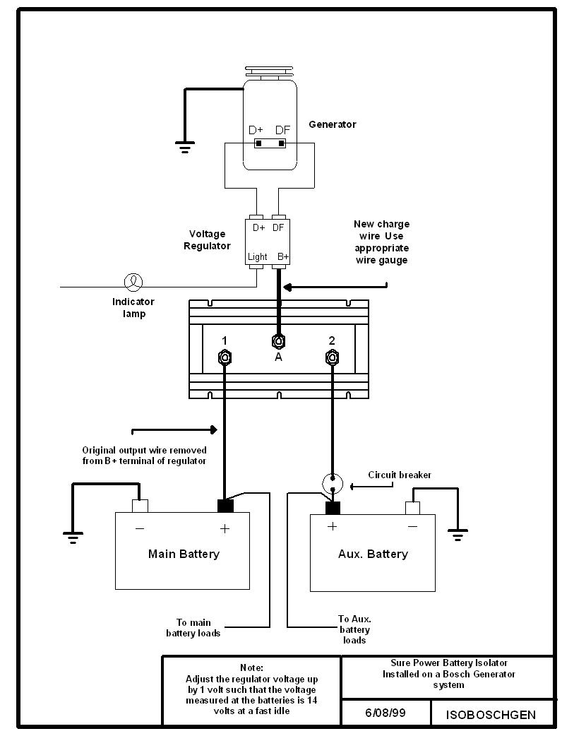
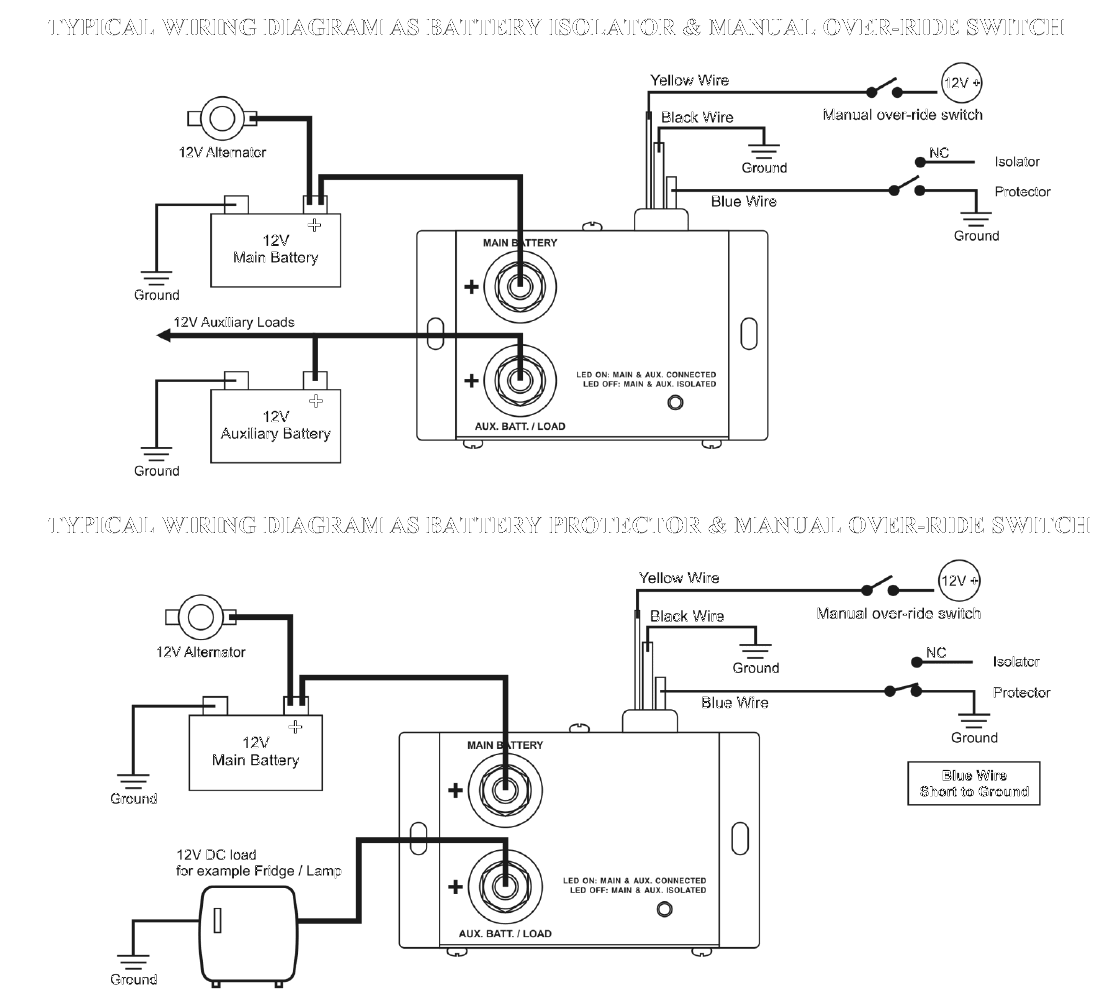
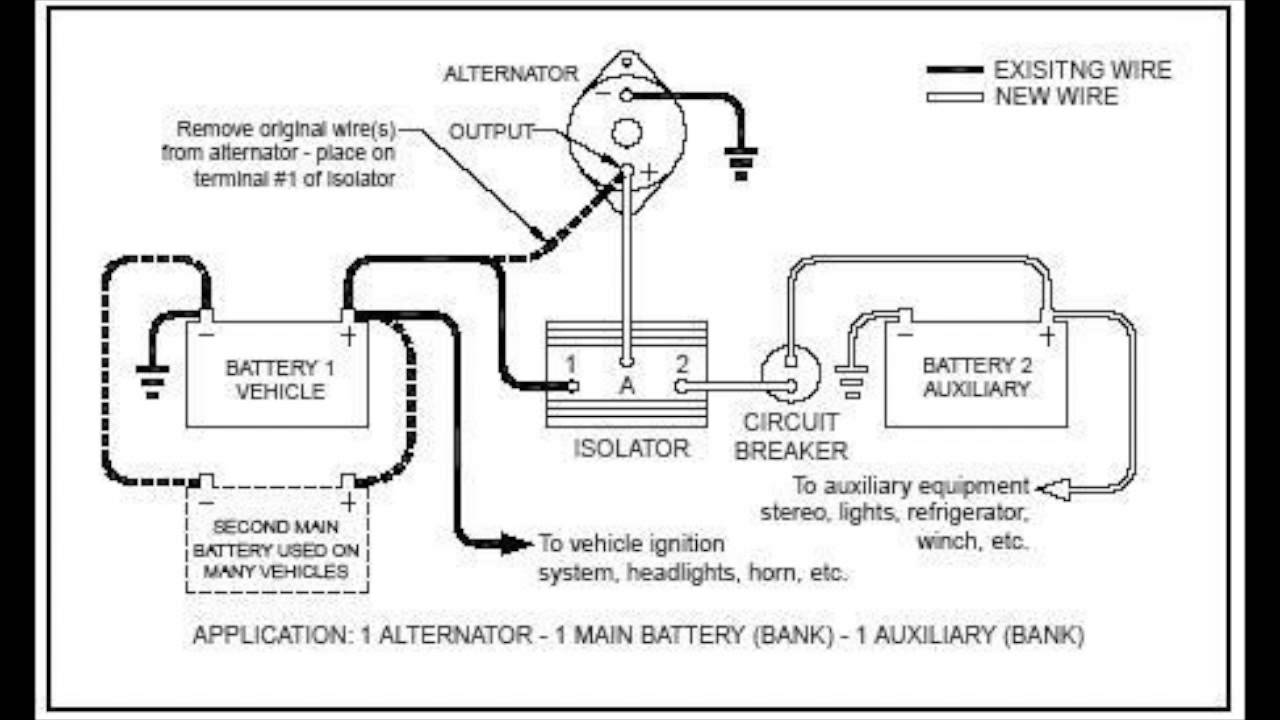
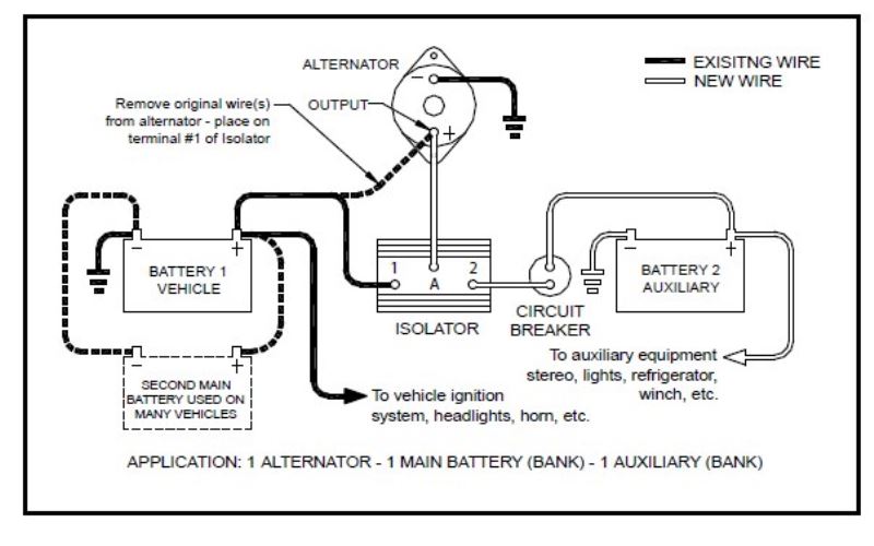
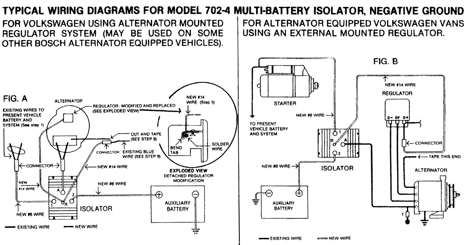
Wire size) to the battery bat terminal of the alternator and the other end to the a terminal of the isolator. Route the other end of the yellow wire to the e terminal of the isolator. This wire is simply used as a ground for activating the relay.
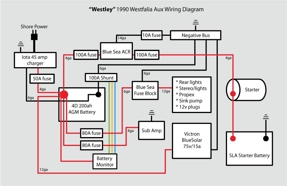
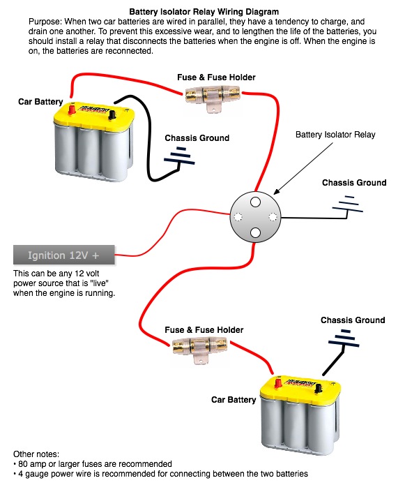
Wellborn assortment of multi battery isolator wiring diagram. It shows the elements of the circuit as simplified forms, and the power as well as signal connections between the devices. Prevents auxiliary power from draining the starter battery.
First, make sure you have all the tools, wire, connectors and circuit breakers you will need. Once you have hooked up the isolator you can do the actual wiring. Allows each battery to charge according to its own needs.
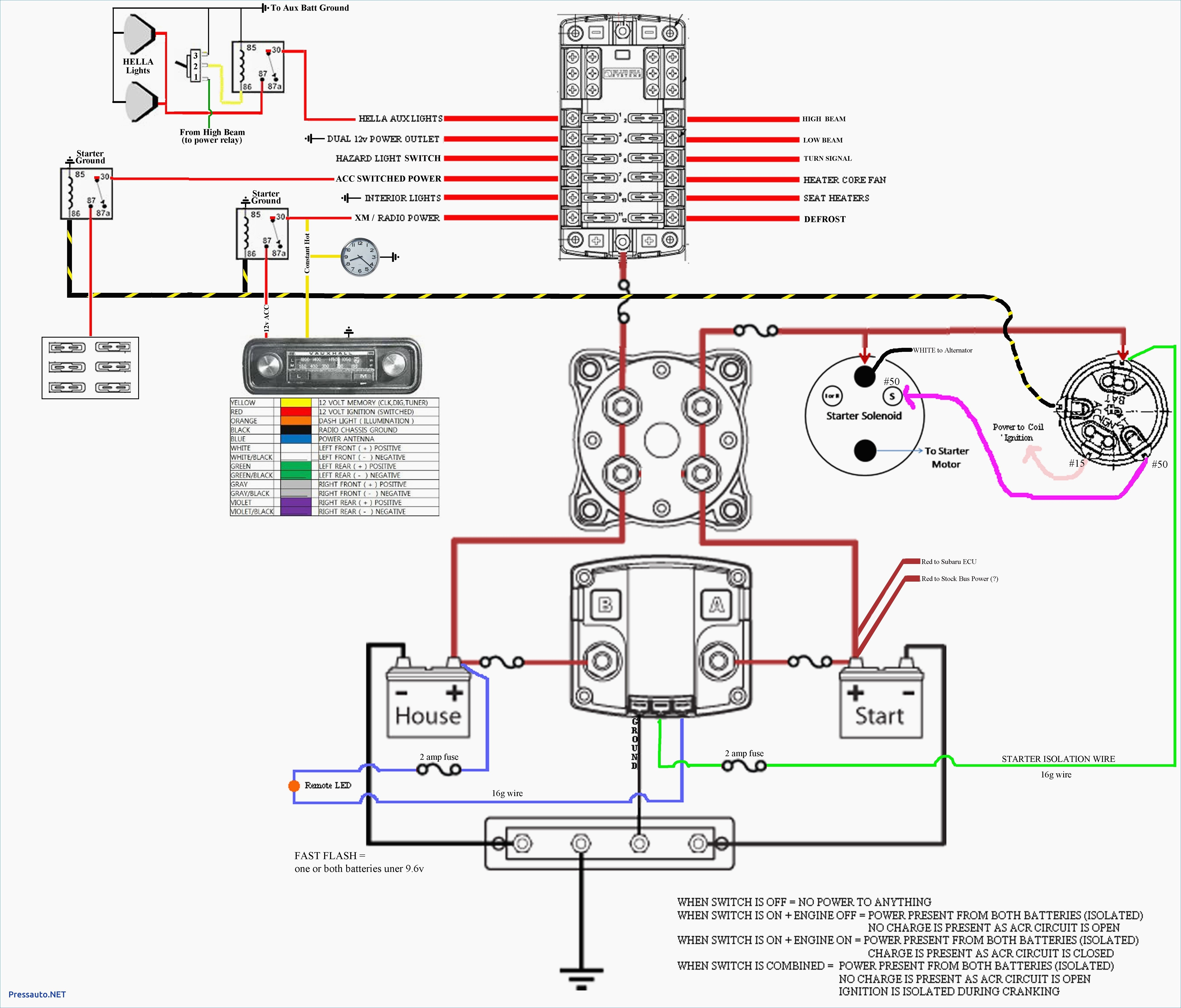
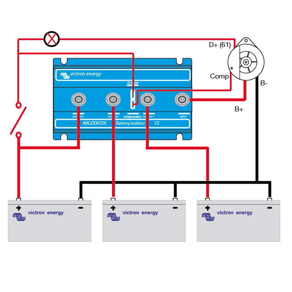
With such an illustrative guidebook, you will have the ability to troubleshoot, prevent, and total your projects without difficulty. One terminal on the relay should be connected to the positive terminal of the primary starting battery using 6ga red wire. Below you will find the basic design of 3 types of battery isolators with the pros and cons of each.
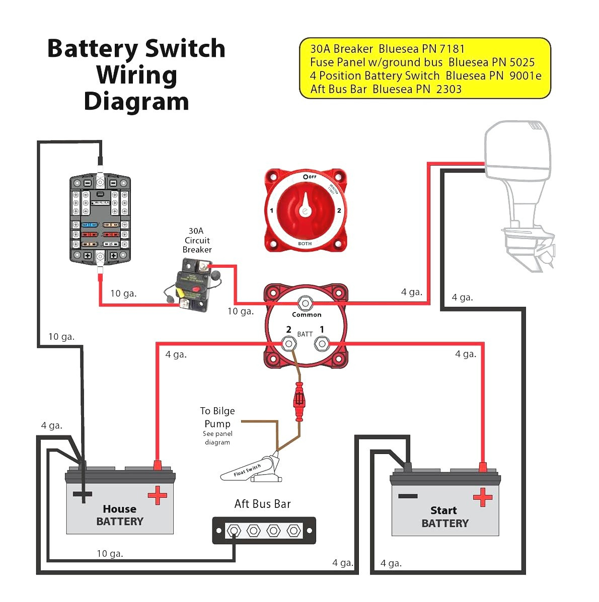
Battery isolators may be used with selector switches. Use the rv electrical diagram we made below to get an understanding of what powers what and to learn how an rv electrical system works. Battery isolators make sure you are never stranded with a dead starter battery.
(looking at the wiring diagrams for both the 60 and 62's shows the external wiring is the same.) i spoke to sure power's. Multi battery isolator wiring diagram january 3, 2021 by larry a. Then, take the negative cable from your actual car battery and remove it.
Circuitry layouts are made up of two. Keep in mind during this step that you have to disconnect the negative cable before you attach the positive terminal to anything so that you do not get shocked. First, make sure you have all the tools, wire, connectors and circuit breakers you will need.
First, make sure you have all the tools,. In this video we talk about the two types of batter. Learn more about battery isolators and why you need one if your car audio system has 2 or more batteries.
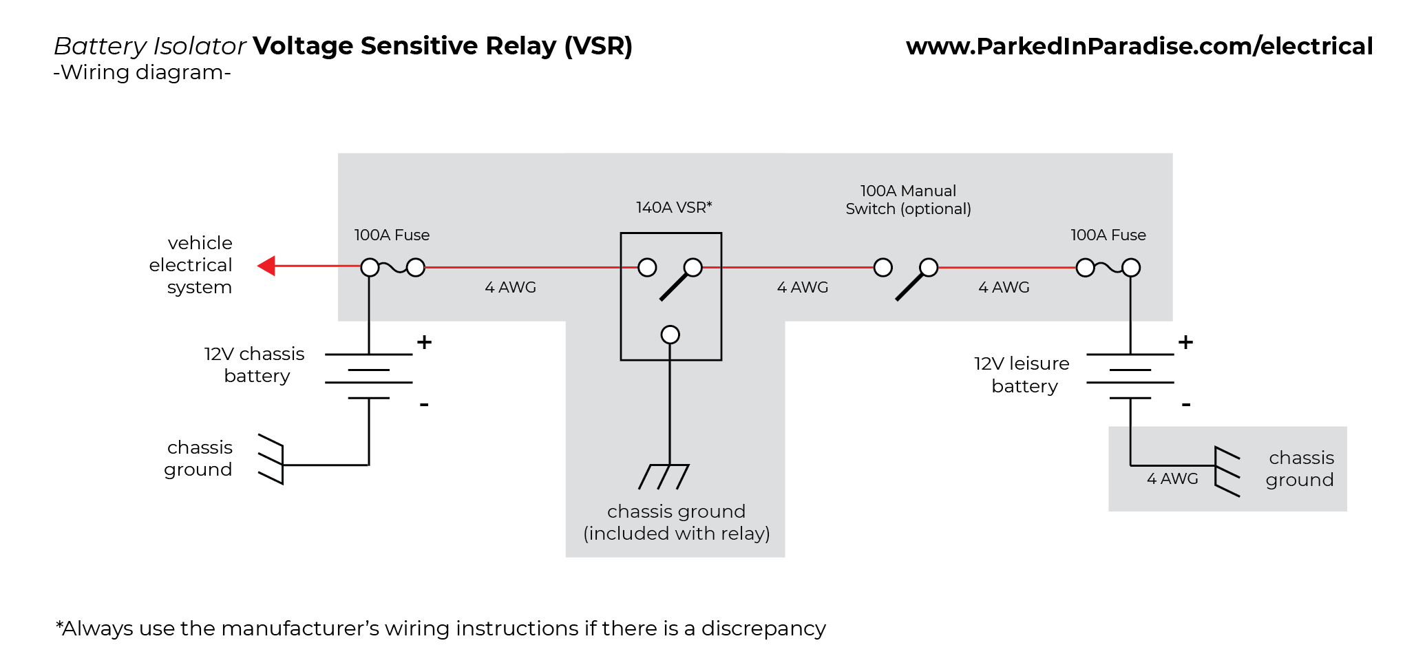
Obtaining from point a to direct b. After answering numerous questions about different battery isolator schemes, i decided it would be easier to just build a webpage. The black wire coiled inside the relay needs terminated to a good ground location using the included blue crimp connector.
Another thing you will discover a circuit diagram would be traces. Battery isolator wiring diagram dual battery setup truck camping trucks dual battery diagram for rv will definitely help you. A wiring diagram is a simplified conventional photographic representation of an electrical circuit.
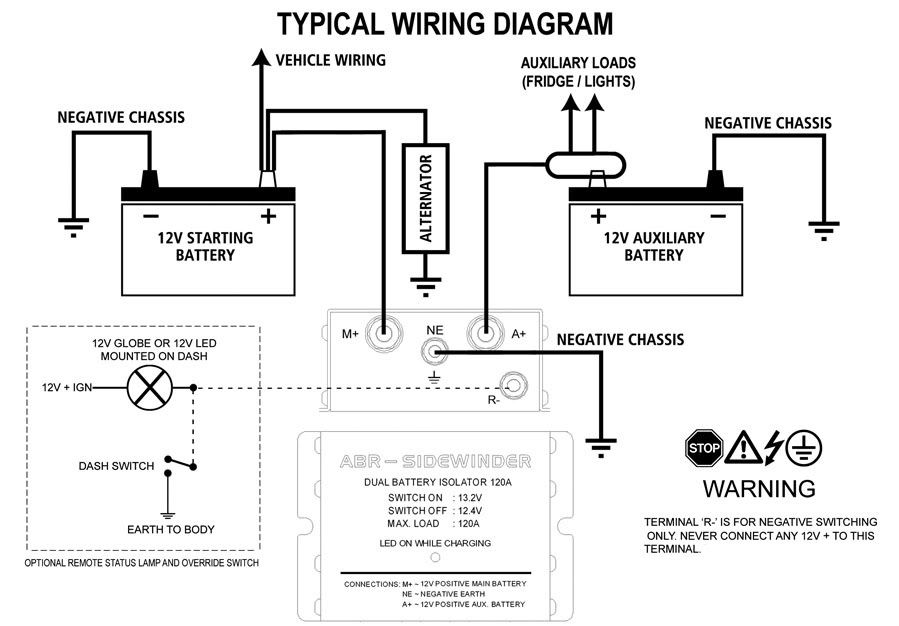
When charging the starting battery the isolator will automatically connect the auxiliary battery when the starting battery reaches 13.4v. Multi battery isolator wiring diagram sample. Wiring diagram wiring the relay:
Wiring diagram for battery isolator use with two 6 volt golf cart batteries how to charge up a trailer mounted battery while driving how to wire a two battery universal isolator # dw08771 on 2002 ford e450 Each component ought to be placed and connected with other parts in specific manner. I allows your house and start battery to remain isolated except for emergency conditions.
With this kind of an illustrative guide, you'll be capable of troubleshoot, avoid, and full your projects without difficulty. The objective is the very same: There are two things which are going to be found in any dual battery isolator wiring diagram.
Marine wiring diagrams without selector switches are shown in figures 1, 2 and 3. A circuit is generally composed by various components. You can charge the auxiliary battery with a battery charger without affecting the battery isolator at any time.
This should now be the only wire connected to either of these terminals.
Dual Battery Isolator Wiring Diagram Wiring Diagram

[FY_0535] Miopro Battery Isolator Diagram Wiring Diagram

Sure Power Battery isolator Wiring Diagram Collection
Motorhome Battery Isolator Wiring Diagram
Dual Battery Isolator Wiring Diagram Wiring Diagram
12V Battery Isolator Wiring Diagram Wiring Diagram
Sure Power 9523a Wiring Diagram
Noco Battery Isolator Wiring Diagram
Sure Power 9523a Wiring Diagram
Sure Power Battery Isolator Wiring Diagram Wiring Diagram
Multi Battery Isolator Wiring Diagram
Cole Hersee Battery Isolator Wiring Diagram
How to Wire Up a Sure Power 120 Amp Two Battery Isolator
35 Battery Isolator Wiring Diagram Manufacturers Wiring
[DIAGRAM] Car Audio Wiring Diagram For Battery Isolator
Wiring Manual PDF 110 Volt Battery Isolator Wiring Diagram

Sure Power 9523a Wiring Diagram

Dual Battery Isolator Wiring Diagram Wiring Diagram
200 Amp Relay High Current Automotive Battery Isolator